STIP Thruster – Technical Overview
A modular multi-mode thruster architecture that converts simple gases - CO₂, steam, and trace H₂/O₂ into useful propulsion through stacking thermal input from different sources. This document provides a complete technical overview of the STIP (Stacked Thermal Input Propulsion) thruster architecture, presented in the same panel format as the RTC file.
1. System Architecture Summary
The STIP thruster is a modular gas-based propulsion device mounted on deployable spacecraft panels. It receives superheated gas such as CO2 or H2 via the hot-bus network connected to a central thermal core.
2. Gas Bus Flow Architecture
The propulsion system uses two independent flow networks: a cold CO₂ outflow/refill bus into the core and a hot CO₂ return bus feeding the thruster manifolds.
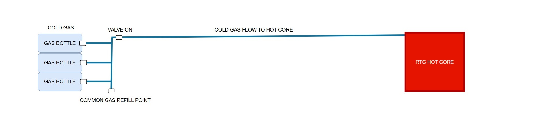
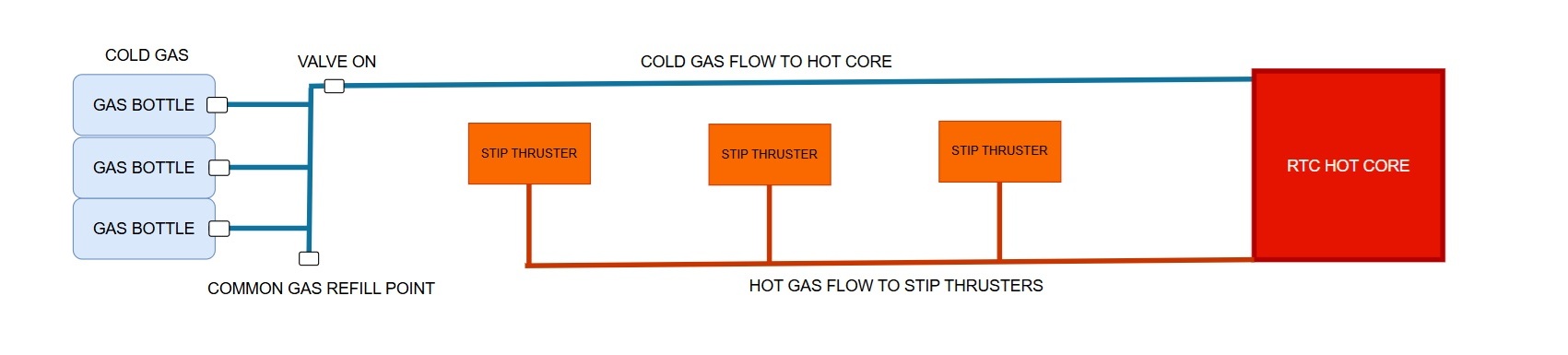
Cold Gas Bus - Flow from Gas Storage to the RTC Hot Core
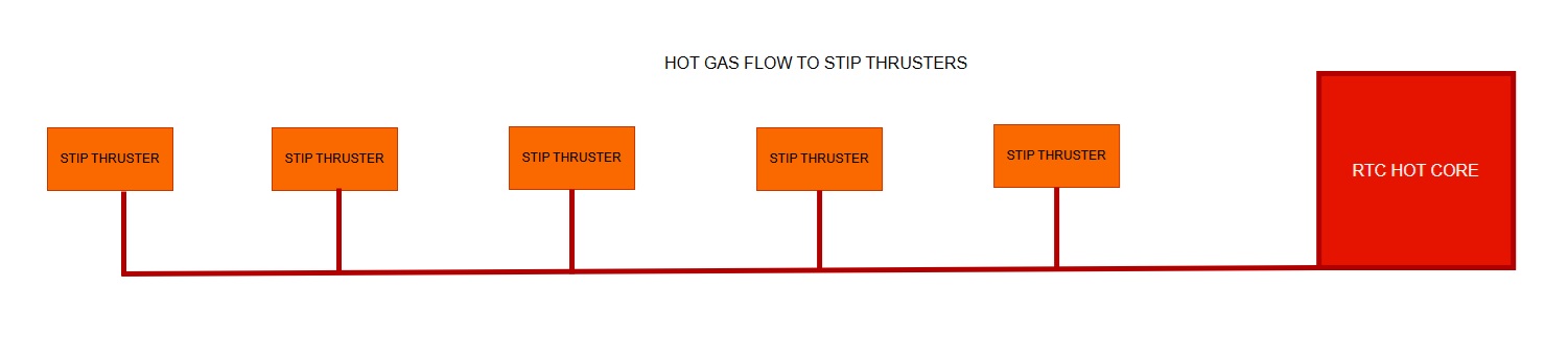
Hot Gas → Thruster Panels
3. Operating Modes
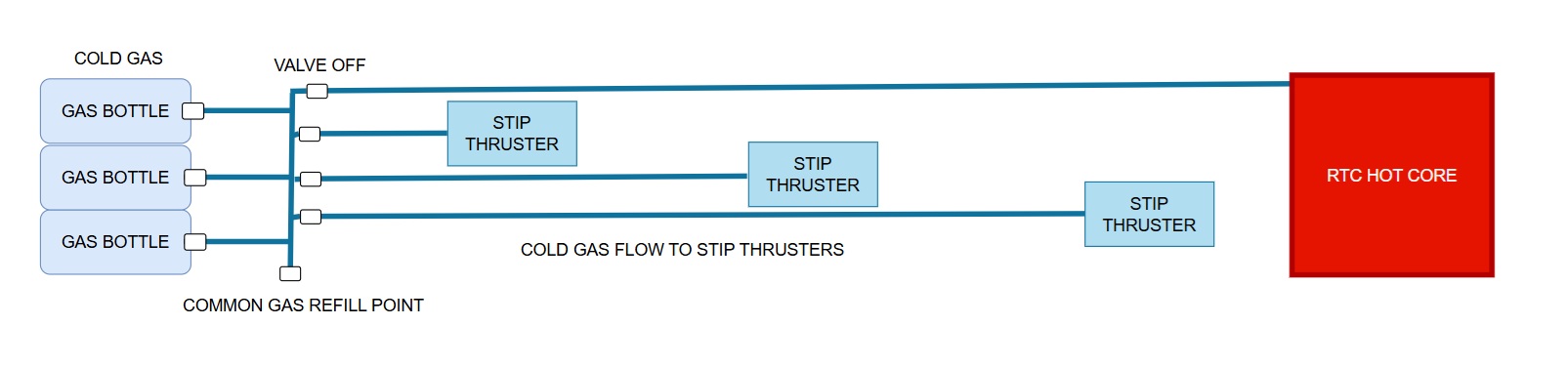
Mode A - Cold Gas Thruster - Station Keeping or Emergencies ISP Estimate ~ 50-80 with CO2
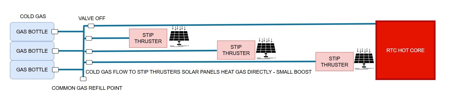
Mode B – Solar Assisted Cold Gas Thruster - Small Efficency Boost ISP Estimate ~ 100-130 with CO2
Mode C – RTC (Hot Thermal Core) Gas Thruster ISP Estimate ~ 150-220 with CO2
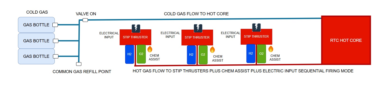
Mode D – RTC plus Chem Augmented Propulsion (CO₂ + H₂/O₂) ISP Estimate ~ 200-280 with CO2

Mode E – Plasma mode - RTC plus Chem Assist Propulsion plus Electrical Input ISP ~ 300-600 with CO2
4. Plasma Mode Operation
Plasma Mode (High-Isp Partial Ionisation Stage)
Plasma mode is the highest-efficiency operating regime of the STIP thruster. In this mode, electrical energy is added to the already hot, chemically augmented gas flow to achieve partial ionisation and elevated exhaust temperatures. Plasma mode is not used for ignition; it is strictly a performance enhancement layer applied after the tube is fully thermally conditioned.Flow Structure and Zone Layout
A plasma-capable STIP tube is divided into three functional regions:a. Vortex and Mixing Zone
Hot carrier gas from the RTC enters tangentially through wall inlets, establishing a stable vortex core. Hydrogen and oxygen are injected separately into the axial region of this swirl, ensuring they only meet inside an already hot flow. Auto-ignition occurs at ~500–600 °C.b. Chem-Assist Thermal Zone
The hydrogen-rich burn occurs within the swirling core, away from the tube walls. This zone provides a significant temperature rise and establishes a uniform, high-enthalpy gas mixture before plasma coupling.c. Plasma Addition Zone (Downstream)
Located after the primary combustion/mixing region, this section contains the plasma coupling hardware. Here the gas is hot, well-mixed, and electrically conductive, allowing efficient energy deposition at modest ionisation fractions (≈1–5%).Electrode and Coil Geometry
The plasma zone is integrated into a replaceable nozzle cartridge, which includes: Annular electrode rings or a central–wall electrode pair, or, alternatively, external RF/induction coils with no direct internal contacts. This modular hot-end design localises thermal and electrical wear to a consumable component and allows upgrades without altering the upstream tube body.Operating Principle
Plasma mode adds electrical power to the gas to raise enthalpy beyond chemical and thermal limits. Only a small ionisation fraction is required: Improves effective exhaust temperature Reduces molecular weight of some species Enhances γ and energy extraction efficiency Achieves values in the 1200–1800 isp range for hydrogen flows Because the gas is already extremely hot, electrical power requirements are modest compared to full plasma thrusters.Control Strategy
Plasma mode is enabled only when: Carrier gas temperature and tube-wall temperature exceed defined safety thresholds Chem-assist (if active) is stable Mass flow is within plasma-safe limits The controller ramps electrical power gradually to maintain arc or EM-field stability while avoiding electrode overheating. Plasma tubes typically operate in sequential duty cycles to extend consumable life, while non-plasma tubes continue in thermal or chem-assist modes.Safety Characteristics
Plasma mode does not initiate combustion and cannot ignite H₂/O₂ mixtures on its own. It operates strictly downstream of the auto-ignition region and only on gas that is already hot and well-mixed. The electrodes or coils are never exposed to cold reactants or unburned pockets.Functional Role in STIP
Plasma mode is used for: High-Isp cruise Precision manoeuvres Deep-space Δv trimming Energy-efficient long-duration burns In bulk thrust operations, all tubes run in thermal or chem-assist modes, and plasma tubes behave as standard tubes with electrodes inactive.5. Hydrogen and Oxygen Buses
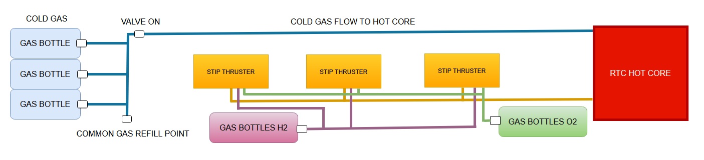
Hydrogen and Oxygen require separate unheated Buses connected to the STIP Thrusters for Chem Assist. Chem Assist mode must only be run with the RTC hot core online as Chem Assist relies on the heat from the RTC to ignite H2/O2 in the tube
1. Performance Advantages
Hydrogen offers the highest Isp values available within the STIP architecture: Thermal H₂ (RTC-heated): ~700–900 s Chem-assist H₂: 1 000–1 300 s Partial plasma H₂: 1 200–1 800 s These performance levels: Enable ~3–5 month Mars transfers Allow ~1–2 day Earth–Moon transit times Reduce propellant mass for a given Δv Greatly extend usable Δv for deep-space missions Hydrogen effectively defines the high-performance operating window of STIP.2. Non-Cryogenic Hydrogen Storage (Automotive-Derived but Space-Adapted)
STIP does not require cryogenic liquid hydrogen. It uses ambient-temperature high-pressure hydrogen, the same broad category employed by fuel-cell cars. However, automotive tanks cannot be used directly without modification.2.1 Automotive Carbon-Fibre Tanks as the Baseline
Europe already mass-produces 700–1 000 bar carbon-fibre hydrogen tanks for fuel-cell vehicles, providing: Mature, high-throughput manufacturing Proven pressure and safety performance Certified handling and regulation systems Extensive industrial supply chains But these tanks must be adapted for space, not used unchanged.2.2 Required Adaptations for Space Use
To survive vacuum, radiation, and thermal extremes, space-qualified versions include: Low-outgassing, radiation-tolerant resins Modified liners (polymer blends or thin metal liners with better vacuum behaviour) Deep insulation (MLI blankets, foam layers, or integrated thermal shielding) Protection from UV and charged particle radiation (tanks placed under hull panels or solar wings) Micrometeoroid shielding (Whipple shields or structural back-plates) Multiple smaller tanks instead of a single large unit, improving fault tolerance All these changes preserve the manufacturing method while adapting the materials and mounting.2.3 Resulting Benefits
No cryogenic systems required Tanks remain light and high-pressure capable Hydrogen permeation is manageable in vacuum Safety remains high through shielding and redundancy Automotive production lines can adapt without major redesigns The outcome is a space-qualified composite hydrogen tank lineage derived directly from Europe’s automotive hydrogen economy.3. Compatibility With Europe’s Hydrogen Economy
Europe is already deeply invested in hydrogen through: The EU Green Deal and hydrogen corridors Large electrolyser production capacity Extensive FCEV bus/truck adoption Composite pressure-vessel manufacturing This means Europe already possesses: Carbon-fibre filament-winding factories Certified pressure-vessel QA procedures Valve/regulator suppliers Hydrogen-handling expertise Hydrogen safety testing infrastructure Space-adapted composite tanks can be built on the same lines, with upgrades to resins, liners, and environmental testing. This makes hydrogen a strategic propellant choice that aligns STIP propulsion with existing European strengths.4. Industrial Repurposing Potential
Using hydrogen enables: Automotive composite tank manufacturers to enter the space sector ICE-era exhaust/turbo plants to build manifold hardware Fuel-cell regulator suppliers to produce aerospace-grade H₂/O₂ valves Composite and carbon-fibre industries to expand into high-value space markets For Europe, this is a direct way to preserve industrial capability while transitioning to the post-ICE era.5. Operational Model With Hydrogen
When used as a primary working gas: Hydrogen is heated by the RTC core to operational temperature Chem-assist adds controlled H₂/O₂ burn inside the vortex core Plasma mode provides high-Isp partial ionisation Nozzle cartridges handle the highest-energy flows and are replaced at depots Tanks are mounted in cold, shielded sections of the hull, away from hot bus lines Hydrogen becomes the high-efficiency tier of the STIP system, while CO₂ and O₂ remain the economical and easily sourced propellants for early lunar and orbital operations.6. Summary
Hydrogen offers: The highest achievable performance in STIP Non-cryogenic storage with adapted automotive tank technology Safe operation via shielding, insulation, and vacuum-qualified materials Direct industrial leverage for Europe’s hydrogen and composite sectors Fast, efficient transfer capability for Moon-to-Mars-to-deep-space missions Hydrogen is not just a propellant choice; it is a strategic alignment of physics, engineering, and European industrial capacity.6.Workforce Transition and Industrial Integration and Manufacturing
STIP manufacturing aligns with ICE-era factories globally: Toyota, BMW, VW, Ford, Hyundai, Lada, Chrysler, and others.
7. Maintainability Philosophy
All STIP thruster panels are modular, isolatable and removable. Couplers and valves follow accessible mechanical procedures similar to automotive service.
STIP Thruster Consumables and Service Model
The STIP architecture deliberately concentrates wear into a small set of inexpensive, replaceable components so that the main thruster structure remains long-life and low-maintenance. All high-stress elements—thermal, chemical, or plasma—are confined to a nozzle cartridge that attaches to the downstream end of each STIP tube. This creates a predictable servicing workflow and enables a robust “depot economy” for propulsion maintenance.
a. Nozzle Cartridge Concept
Each STIP tube terminates in a short, modular nozzle cartridge containing: The throat and expansion geometry The highest-temperature flow surfaces The plasma electrodes or RF coupling hardware (for plasma-capable tubes) Optional internal liners to protect upstream structure Temperature and erosion sensors as needed The rest of the tube—vortex inlet, H₂/O₂ injector zone, and structural shell—is designed for long service life. All significant wear is confined to the cartridge.b. Wear Mechanisms by Operating Mode
Different propulsion modes produce different erosion environments: Thermal Gas Mode (CO₂ or H₂ only) Primary wear: thermal cycling, minor throat erosion Cartridge lifetime: very long; replaced only during extended depot overhauls Chem-Assist Mode (H₂/O₂ injection) Higher peak temperatures Reactive species (H₂O and radicals) increase throat oxidation Cartridge lifetime: moderate; replaced periodically depending on duty cycle Plasma Mode (partial ionisation) Additional ion/electron bombardment Localised surface sputtering Strongest thermal gradients Cartridge lifetime: shortest; replaced more frequently based on plasma runtime The same cartridge interface supports all three modes, but service intervals differ.c. Benefits of the Consumable Hot-End Design
Predictable maintenance: tubes are inspected and cartridges replaced at scheduled depot stops Minimal downtime: swapping a cartridge is a fast mechanical operation Upgradeable performance: new nozzle ratios, electrode alloys, or coatings can be introduced without redesigning the upstream tube Safety: high-wear and high-risk zones are isolated into a small, inspectable module Commercial ecosystem: enables a manufacturing pipeline for nozzle cartridges, liners, electrodes, and specialised plasma variants This model mirrors aviation and automotive practice: the durable engine body remains in service, while the hot-end consumables are replaced regularly to maintain efficiency and reliability.d. Tube Longevity
Because the high-wear operations occur downstream: The vortex inlet, injector manifold, and tube body experience comparatively mild thermal loads Material fatigue is low Structural lifetime is high Most tubes remain in service for thousands of hours between inspections Only the cartridge is routinely replaced.e. Depots as Service Nodes
Orbital and lunar depots serve as natural maintenance locations: Refuel propellant tanks (CO₂, H₂, O₂) Swap nozzle cartridges for plasma-heavy missions Inspect injectors and sensors Run test burns to verify performance Upgrade cartridges if improved designs are available This creates a self-sustaining service economy around reusable spacecraft, increasing uptime and enabling frequent Earth–Moon and interplanetary cycles8. Industrial Scaling Potential
Engine plants, metal fabrication lines, and robotic welding systems can be repurposed for high-throughput STIP production.
9. Global Automotive Industrial Compatibility
STIP components map directly to existing capabilities used in turbochargers, exhaust systems, and sensor-actuator assemblies.
10. Why ICE Manufacturing Maps Naturally to STIP Production
Repeatable subassemblies, thermal alloys, and robotic welding all transfer directly to STIP thruster production.
11. ESA, National Space Agencies, and Industrial Strategy
STIP provides a sovereignty-friendly propulsion supply chain for agencies transitioning industrial bases.
12. Workforce Transition Model
Technicians retrain in high-temperature sealing, vacuum assembly, and pressure testing.
13. Manufacturing Economics and Scaling
High-volume automotive workflows enable low-cost thruster production.
14. Failure Modes and Redundancy Strategy
Panels are independently isolatable; failures do not disable the system.
15. Thermal and Mechanical Lifecycle Considerations
Components are designed for thousands of thermal cycles with predictable wear and replacement intervals.
16. Valve Sequencing and Control Logic
Hot-bus valves open only when panels are mechanically latched and thermally ready.
17. Hot Bus Pressure and Temperature Envelope
The hot bus supports both augmented peaks and sustained thermal thrust modes.
18. Internal Structure of a STIP Tube
Includes preheat zone, main heating stage, stabilisation section, and exhaust shaping.
19. Thermal Core to Hot Bus Flow Path
The regenerator heats CO₂ which then flows through distribution headers to deployed panels.
20. Integration with Spacecraft Systems
AI-driven control manages mode selection, thermal balance, and thrust vectoring.
21. High-Level Safety and Interlock Principles
Mechanical, thermal, pressure, and control interlocks ensure safe operation.